
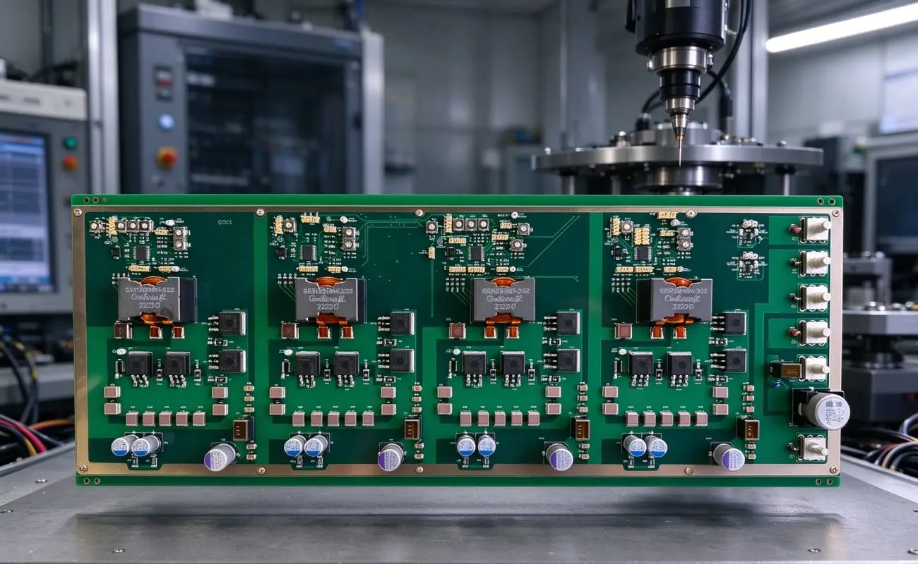
Motor drive systems play an important role in industrial automation, including conveyor equipment, pumps, fans, and other factory machinery. These applications require circuit boards that can support power distribution, signal processing, and reliable connections between electronic components. Choosing a suitable 4-layer industrial control PCBA helps engineers organize complex circuits while maintaining a practical balance between electrical performance and mechanical stability. However, selecting the right assembly involves more than counting PCB layers. Engineers should also evaluate the board material, copper thickness, stackup design, component mounting methods, and manufacturing quality.
Why a Four-Layer Structure Matters for Motor Drive Applications
Compared with a basic two-layer design, a multilayer PCB provides additional routing space and more flexibility for separating power and signal circuits. For industrial motor drives, this structure can help reduce unwanted electromagnetic interference when the signal, power, and ground layers are properly designed. In this product configuration, the four-layer stackup consists of two signal layers and two power or ground planes. The inner planes also support 24V DC power distribution, helping organize connections for control circuits and related components.
A well-planned layer architecture offers several practical benefits:
- Improved signal organization: Separate signal routing layers provide more space for control and feedback circuits.
- Power distribution support: Dedicated power planes help distribute 24V DC across the board.
- EMI management: Ground and power plane arrangements can help reduce interference when combined with appropriate layout and grounding practices.
- Flexible component placement: Additional routing space supports the integration of microcontrollers, relays, connectors, and signal conditioning components.
Nevertheless, the layer count alone does not guarantee stable operation. Engineers should review current paths, grounding strategies, switching noise, and component placement during the PCB design stage.
Key Factors When Selecting an Industrial Control PCB Assembly
1. Choose a Suitable FR4 Material and Board Structure
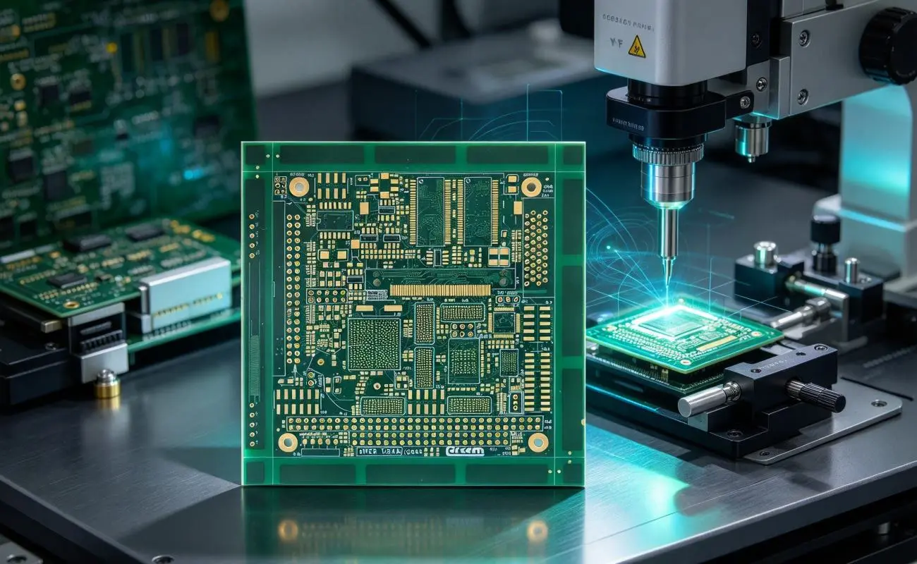
Material selection directly affects electrical insulation, mechanical strength, and long-term reliability. FR4 PCB materials are widely used in industrial electronics because they provide a practical combination of insulation properties and structural stability. The described board uses FR4 material with a dielectric constant of 4.5, a thickness of 1.5mm, and an overall size of 350 × 125mm. This large-format design provides space for high-power devices, relays, and connectors while supporting installation in industrial control cabinets.
2. Evaluate Copper Thickness and Current Distribution
Copper thickness is another important consideration, particularly when a board handles power distribution for motor drivers and solenoid valves. The specified 1oz copper layer, equivalent to approximately 35μm, is designed for moderate current loads, with the supplied product information listing up to 10A per trace. However, actual current capacity depends on trace width, copper temperature rise, ambient conditions, and cooling arrangements. Therefore, engineers should calculate current requirements for each power path instead of relying on copper thickness alone.
3. Select an Appropriate Surface Finish and Solder Mask
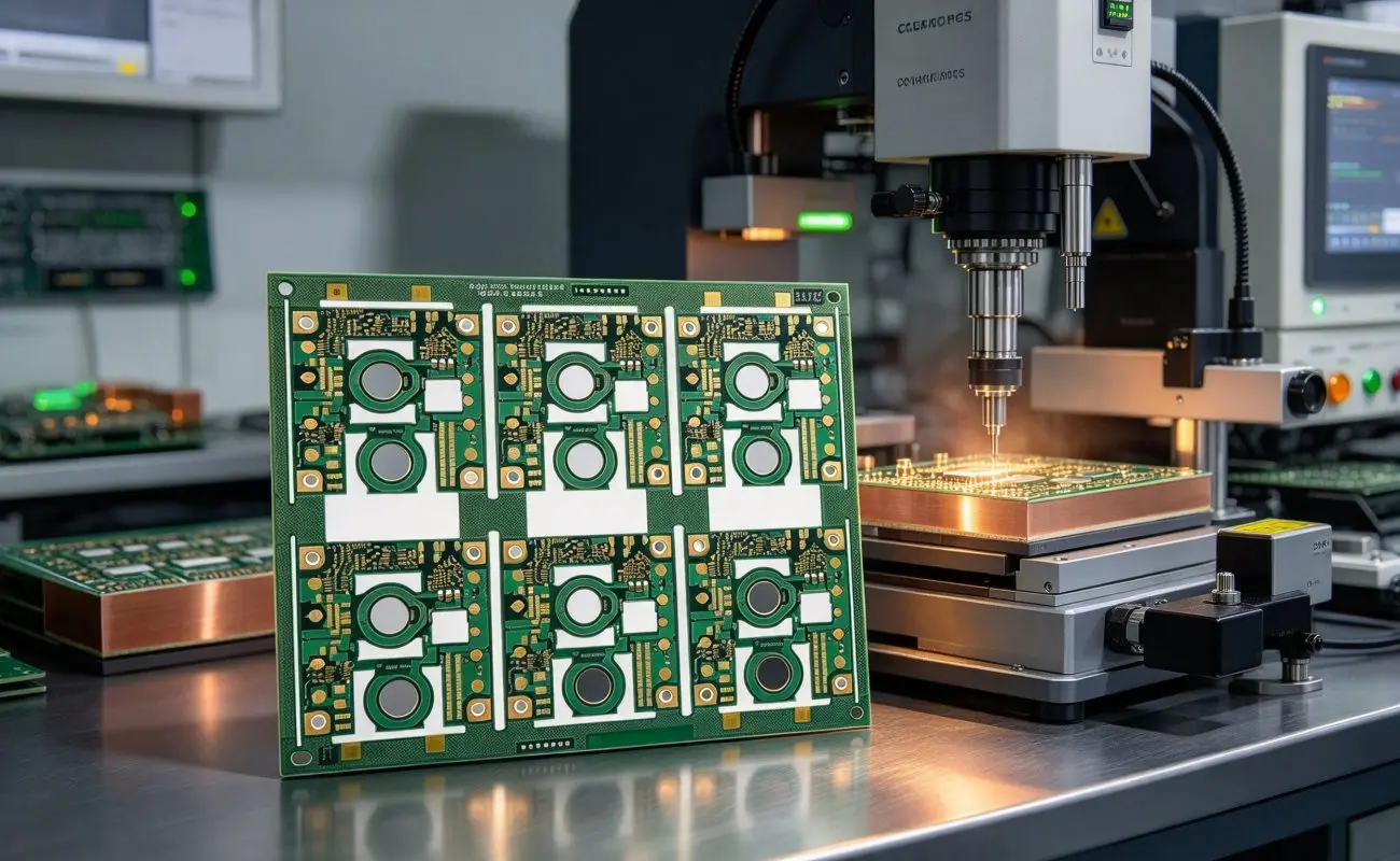
Industrial control boards may operate in environments exposed to oils, coolants, cleaning agents, and temperature fluctuations. A green liquid photoimageable (LPI) solder mask provides a standard surface for visual inspection and helps protect copper traces from environmental exposure. Meanwhile, the ENIG surface finish uses a nickel layer of 3–5μm and a gold layer of 0.05–0.1μm, according to the supplied specifications. This finish supports solderability and helps protect exposed copper areas from corrosion during storage and assembly.
4. Match SMT and DIP Assembly to Component Requirements
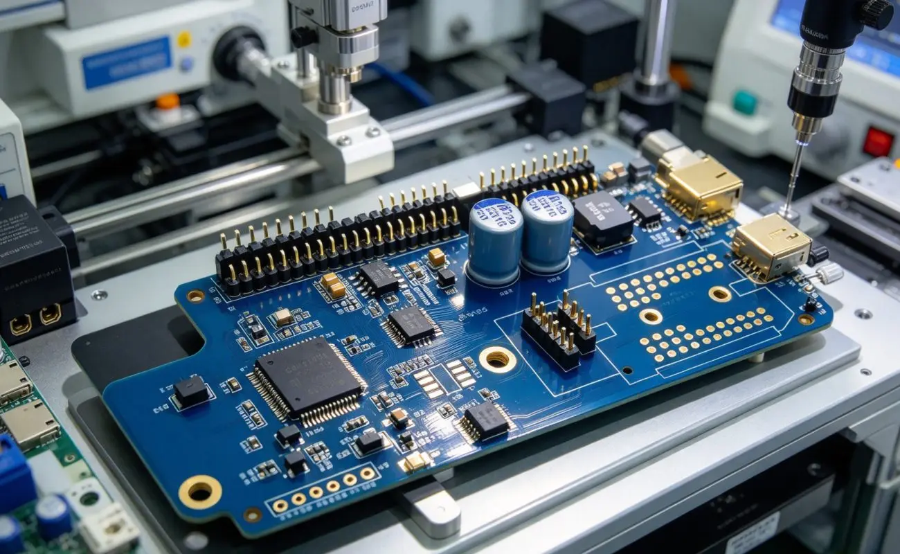
Motor drive boards often combine compact control components with connectors that need secure mechanical connections. SMT assembly supports high-density placement of microcontrollers and signal conditioning ICs, while DIP assembly is suitable for through-hole components such as terminal blocks and DB9 connectors. Combining both methods allows the PCB assembly process to accommodate different component sizes and connection requirements. As a result, engineers can balance circuit density with the practical needs of field wiring and maintenance.
Technical Specifications to Compare
Before selecting an industrial PCB for a motor drive project, buyers should compare its electrical, mechanical, and manufacturing specifications. The following table summarizes the key details of this four-layer FR4 board.
| Specification | Product Details |
|---|---|
| Board Type | 4-Layer Industrial Control PCB |
| Base Material | FR4 |
| Board Dimensions | 350 × 125mm |
| Board Thickness | 1.5mm |
| Dielectric Constant | εr = 4.5 |
| Layer Structure | 2 signal layers + 2 power/ground planes |
| Copper Thickness | 1oz (35μm) |
| Power Distribution | 24V DC |
| Listed Current Load | Up to 10A per trace, subject to design conditions |
| Solder Mask | Green LPI |
| Surface Finish | ENIG |
| Nickel Layer | 3–5μm |
| Gold Layer | 0.05–0.1μm |
| Assembly Process | SMT + DIP |
| Line Width/Spacing | 75μm |
| Inspection | 100% AOI and flying probe testing |
| Electrical Testing | Continuity ≤0.1Ω; isolation ≥100MΩ |
| Vibration Testing | 5–500Hz, 2G |
| Compliance | IPC-6012 Class 2, RoHS, REACH |
Manufacturing Quality and Testing Considerations
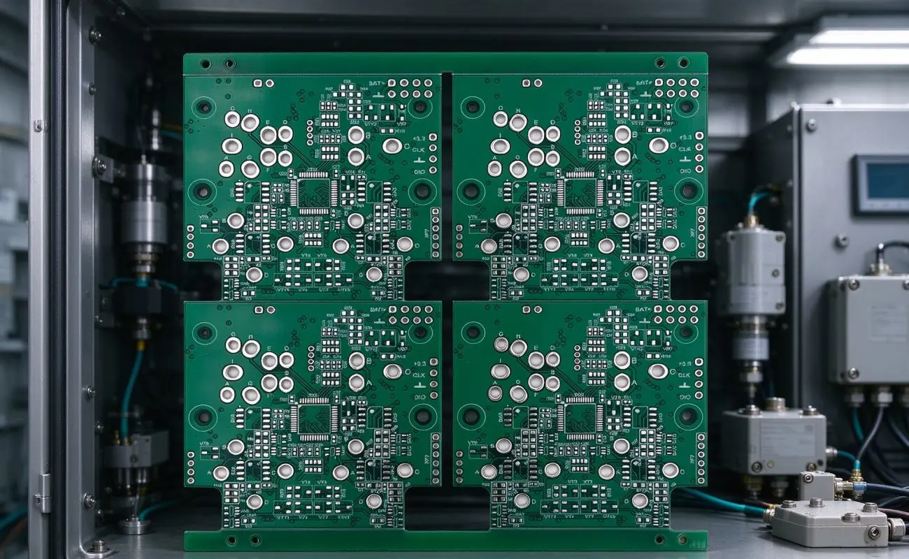
Even a well-designed industrial PCB can experience problems if fabrication and assembly processes are inconsistent. For this reason, buyers should evaluate the PCB board manufacturer based on its process control, inspection methods, and ability to maintain consistent quality across production batches. These factors are particularly important when producing a 4-layer industrial control PCBA for motor drive systems, where stable electrical connections and consistent assembly quality are essential. Large-format boards require particular attention to imaging accuracy, copper plating uniformity, solder mask coverage, and component placement.
For this board, the manufacturing information includes laser direct imaging (LDI) with 75μm line and spacing accuracy, as well as electrolytic copper plating with thickness verification. Quality inspection also includes 100% automated optical inspection (AOI) and flying probe testing. The specified electrical tests check continuity at ≤0.1Ω and insulation at ≥100MΩ, while vibration testing at 5–500Hz and 2G simulates mechanical conditions associated with industrial equipment.
When reviewing an assembly supplier, consider the following points:
- Fabrication capability: Confirm that the manufacturer can produce the required board dimensions, layer structure, and fine line spacing.
- Assembly experience: Check whether the production team can handle both SMT and DIP components.
- Inspection coverage: Review AOI, electrical testing, and other inspection procedures.
- Compliance documentation: Confirm the applicable IPC-6012 Class 2, RoHS, and REACH requirements.
- Production consistency: Evaluate process controls and quality records before moving to volume production.
Fully Hong supports industrial PCB and PCBA manufacturing requirements, helping customers assess board specifications and assembly needs for different electronic applications.
Industrial Applications Beyond Motor Drives
Although motor drive systems are an important application, this type of four-layer board can also support other industrial control projects. Its large format and combination of power and signal layers provide flexibility for applications that integrate multiple electronic components. Depending on the circuit design and operating requirements, potential applications include:
- PLC control panels: Integration of programmable logic controllers, I/O modules, relays, and power supplies for factory automation.
- Conveyor motor drive systems: Power distribution and control connections for variable frequency drive-related equipment.
- Building automation: Circuit integration for HVAC controllers, lighting panels, and security equipment.
- Renewable energy inverters: Support for control and power-related circuits in solar or wind energy conversion equipment.
For each application, engineers should verify operating voltage, current demand, thermal conditions, and electrical safety requirements before finalizing the board design.
Conclusion
Selecting the right 4-layer industrial control PCBA for motor drives requires a balanced evaluation of layer architecture, FR4 material, copper thickness, surface finish, assembly methods, and manufacturing quality. A four-layer structure with dedicated power and ground planes can provide more routing flexibility and support organized power distribution, while mixed SMT and DIP assembly accommodates both compact control components and robust field connectors. At the same time, electrical testing, AOI inspection, and vibration testing provide important quality checks during production.
Before placing a volume order, engineers and purchasing teams should confirm the complete electrical requirements, component layout, environmental conditions, and inspection criteria with their manufacturing partner. By evaluating these factors together, businesses can select a suitable PCB assembly for motor drive systems and other industrial control applications.


Leave a reply