
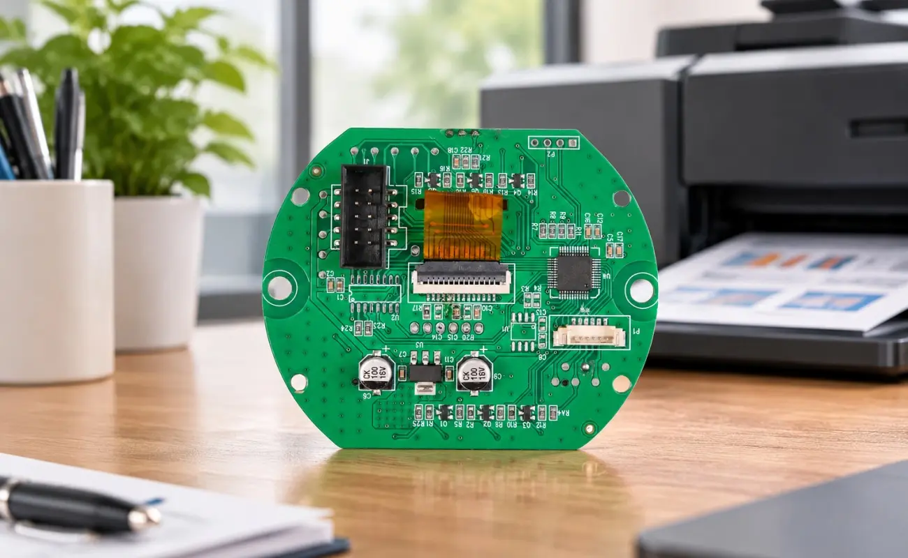
Modern printers rely on multiple electronic components to coordinate printing operations, data communication, and mechanical movement. However, limited internal space can make wiring and signal routing increasingly complicated, especially in industrial printers with moving components. A double-sided printer connectivity PCBA addresses these challenges through a two-sided component layout and integrated Flexible Printed Circuit (FPC) connections. By combining rigid FR4 construction with flexible interfaces, this design supports organized internal connections and reliable electrical communication across different printer systems.
How Does a Double-Sided PCB Architecture Improve Component Layout?
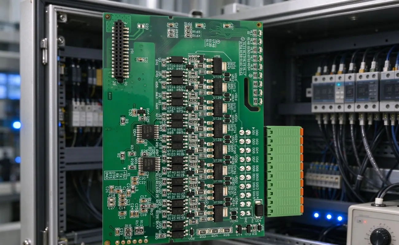
A double-sided PCB provides conductive copper layers on both sides of the board, allowing designers to distribute components and electrical connections more efficiently. In this printer application, the 1.6 mm FR4 board uses a Tg 130 °C material specification to provide mechanical support and stable electrical performance. SMT components, including microcontrollers and driver ICs, are placed on the top layer, while THT components such as power connectors and FPC sockets occupy the bottom layer. Consequently, this arrangement makes better use of the available board area and supports mixed assembly requirements.
The 1 oz copper thickness, equivalent to approximately 35 μm, also contributes to current transmission across the circuit. According to the supplied specifications, the design supports currents of up to 3A for power-demanding components. Moreover, separating different component types across the two sides can help organize power connections and signal interfaces. This approach gives designers greater flexibility when integrating multiple printer functions into a relatively compact electronic assembly.
Why Is FPC Integration Important for Printer Connectivity?
Printers often contain moving assemblies that require electrical connections between components located in different positions. Traditional rigid wiring may create installation challenges when space is limited or when connections need to accommodate repeated movement. Flexible PCB technology provides an alternative by allowing selected connections to bend within a defined radius. Therefore, integrating FPC interfaces into a double-sided printer connectivity PCBA can simplify internal wiring and support connections to moving printer parts.
The board uses 0.5 mm pitch FFC/FPC connectors, including compatible connector options such as the JAE LY series. It supports 50–100-pin interfaces and specifies a minimum bend radius of 5 mm. Additionally, the FPC connection design is rated for more than 10,000 flex cycles, making it suitable for applications that involve repeated movement within the printer.
The main benefits of FPC integration include:
- Flexible internal routing: Helps connect components positioned in different areas of the printer.
- Space-efficient installation: Supports wiring in compact internal structures where rigid connections may be difficult to arrange.
- Repeated movement support: The specified flex-cycle performance accommodates applications involving recurring cable movement.
- Organized interfaces: FFC/FPC connectors provide defined connection points for internal electronic modules.
How Do Electrical Specifications Support Stable Signal Transmission?
Reliable signal transmission depends on appropriate circuit layout, connector selection, and electrical integration. The FR4 board provides a rigid foundation for mounting electronic components, while the copper layers form the conductive paths between them. Meanwhile, the FPC interfaces extend connectivity to components that require flexible connections. Together, these features allow the assembly to accommodate different electrical and mechanical requirements within a printer.
The following table summarizes the main design specifications and their roles in the assembly.
| Design Parameter | Specification | Main Function |
|---|---|---|
| PCB Structure | Double-sided FR4 | Supports two-sided component placement |
| Board Thickness | 1.6 mm | Provides mechanical support |
| Material Tg | 130°C | Defines the specified PCB material grade |
| Copper Thickness | 1 oz / 35 μm | Supports electrical current transmission |
| Current Capacity | Up to 3A | Supports power-demanding components |
| Assembly Method | SMT + THT | Accommodates different component types |
| FPC Connector Pitch | 0.5 mm | Provides compact flexible interfaces |
| FPC Interface | 50–100 pins | Supports multiple signal connections |
| Minimum Bend Radius | ≥5 mm | Defines the specified bending limit |
| Flex Cycle Rating | Over 10,000 cycles | Supports repeated flexing applications |
These specifications should be evaluated together rather than independently. For example, connector pitch affects interface density, while bend radius and flex-cycle requirements influence how designers arrange flexible connections. As a result, reviewing the complete electrical and mechanical layout helps ensure that the selected PCB assembly matches the printer’s operating requirements.
What Role Does IC Programming Play in Printer PCBA?
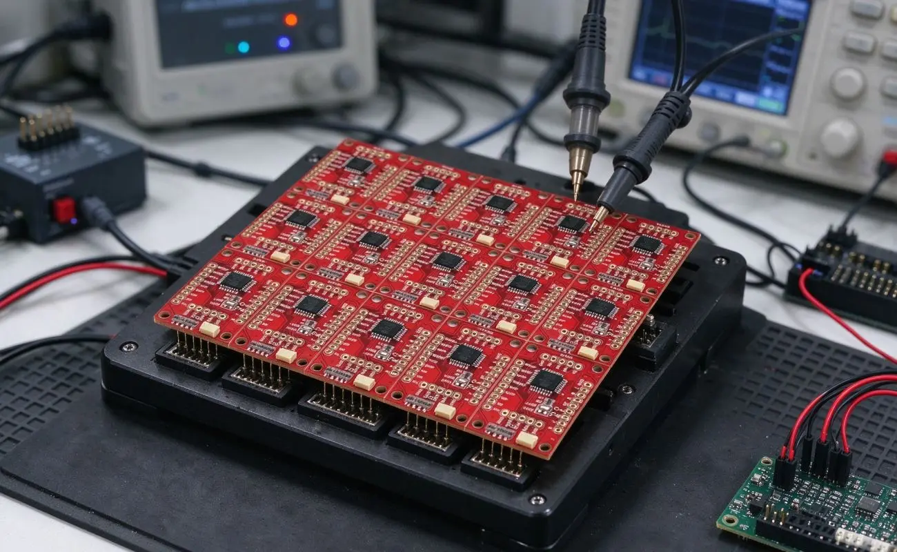
Besides physical connectivity, printer electronics also require appropriate firmware and communication protocols. The board supports in-system programming (ISP), along with JTAG and SWD debugging interfaces, allowing developers to program and debug compatible microcontrollers. Firmware can include print control algorithms and communication functions designed for specific printer applications. Furthermore, USB update support provides another option for firmware maintenance and development.
These programming capabilities offer several practical advantages:
- Pre-programmed firmware: Allows compatible boards to receive firmware before final system integration.
- Debugging support: JTAG and SWD interfaces assist development and troubleshooting.
- USB updates: Provide a convenient firmware update option.
- Functional customization: Supports the development of printer-specific control and communication functions.
Therefore, programming and debugging interfaces contribute to the board’s integration flexibility, particularly when printer manufacturers require application-specific firmware.
Where Is This PCB Assembly Used?
The combination of rigid FR4 construction, flexible connections, and programmable electronics makes this design suitable for different printer configurations. Home printers can benefit from organized component placement and compact internal wiring, while industrial machines may require flexible connections around moving assemblies. In addition, the double-sided layout supports the integration of MCUs, driver ICs, power connectors, and FPC interfaces on one assembly.
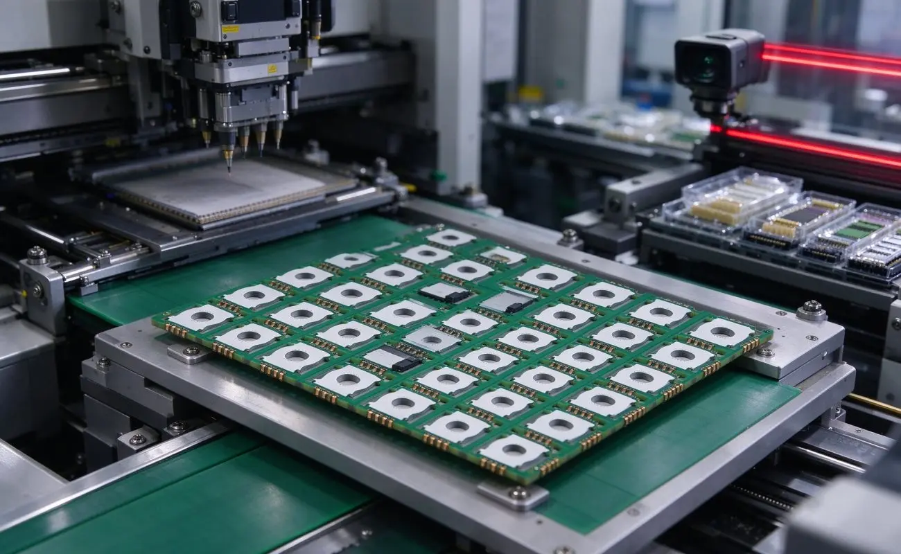
A suitable PCB board assembly should account for the printer’s mechanical structure, electrical requirements, and expected operating conditions. For this reason, designers should evaluate connector positions, cable movement, current requirements, and firmware interfaces before finalizing the design. Working with an experienced circuit board assembly manufacturer can also help coordinate PCB fabrication, component sourcing, SMT and THT processes, and programming requirements.
Conclusion
Printer connectivity requires more than simply placing electronic components on a circuit board. A double-sided layout provides additional component placement options, while FPC integration helps manage connections in compact spaces and around moving printer components. With its 1.6 mm FR4 construction, 0.5 mm pitch FPC connectors, and ISP/JTAG/SWD programming support, the double-sided printer connectivity PCBA offers an integrated approach to printer electronics. Fully Hong combines these design features to support printer connectivity requirements across home and industrial applications.
Leave a reply