
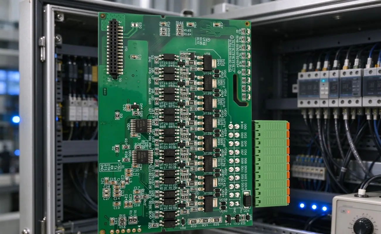
Railway control systems require electronic components that can withstand demanding environmental and electromagnetic conditions. In metro signal monitoring applications, PCBs must process critical signals and maintain stable communication despite vibration, temperature changes, and electrical interference. Therefore, circuit structure, material selection, and manufacturing precision are essential. A custom 4-layer industrial control PCB helps improve electromagnetic compatibility (EMC) through dedicated signal routing and ground and power planes.
Why Is EMC Important in Railway Control Systems?
Railway electronic equipment often operates near communication interfaces, switching devices, and power systems that generate electrical noise. Uncontrolled interference may affect signal transmission, sensor readings, and communication stability. For this reason, railway control boards need careful circuit layout and effective noise management. A four-layer structure helps separate different circuit functions. In this design, two signal layers work with two ground and power planes to reduce interference between sensitive analog circuits and digital signals. Ground stitching vias placed at approximately 5mm intervals also help improve grounding continuity and reduce unwanted electromagnetic emissions.
How Does a 4-Layer PCB Structure Improve Signal Integrity?
Compared with a conventional two-layer design, a four-layer multilayer PCB provides more routing flexibility and better opportunities for controlling interference. Dedicated ground and power planes create stable reference paths, while separate signal routing areas help reduce unwanted coupling. These features are particularly useful for railway controllers handling monitoring signals, communication interfaces, and digital processing.
Several layout techniques can further improve EMC performance:
-
Ground Plane Stitching: Place stitching vias at approximately 5mm intervals to improve grounding continuity.
-
Guard Traces: Add guard traces and via fences around sensitive analog inputs, such as track circuit receivers.
-
Power Line Filtering: Use ferrite beads and bypass capacitors to reduce switching noise.
-
Thermal Via Placement: Add thermal vias beneath power components to improve heat transfer.
Engineers should also consider trace geometry, return current paths, and connector placement during design. Together, these measures help maintain signal quality in railway control equipment.
Why Is ENIG PCB Finish Suitable for Railway Applications?
Surface finishing affects solderability, corrosion resistance, and PCB assembly quality. ENIG PCB finish combines an electroless nickel layer with a thin immersion gold coating, providing a suitable surface for both surface-mount and through-hole components.
The specified board uses 3–5μm nickel and 0.05–0.1μm gold. Its green LPI solder mask protects circuit areas, while white silkscreen markings support component identification during installation and maintenance.
| Technical Feature | Specification | Application Benefit |
|---|---|---|
| Board structure | 4-layer FR4 | Supports complex circuits |
| Dimensions | 85 × 60 mm | Fits compact control cabinets |
| Thickness | 1.55 mm | Provides mechanical stability |
| Copper thickness | 0.5 oz (18μm) | Supports fine-line routing |
| Line/space | 50μm/50μm | Enables dense layouts |
| Surface finish | ENIG | Supports solderability and corrosion resistance |
Combining suitable materials with controlled surface finishing provides a stable foundation for railway electronics.
How Does PCB Assembly Affect Railway Controller Reliability?
Reliable operation depends not only on PCB fabrication but also on component installation and inspection. Railway control boards often combine digital components with connectors and relays, so assembly must address both electrical performance and mechanical stability.
A mixed SMT and DIP process supports different component requirements. SMT is suitable for integrated circuits, resistors, and capacitors, while DIP mounting provides secure connections for DB9 connectors, RJ45 interfaces, and relays.
Key assembly considerations include:
-
SMT Placement: Position components accurately for compact circuit integration.
-
DIP Installation: Secure connectors and relays through suitable through-hole mounting.
-
Process Control: Maintain consistent soldering conditions to reduce defects.
-
Electrical Testing: Use in-circuit testing to verify component and circuit functionality.
Thermal management is equally important. Thermal vias beneath regulators and power drivers transfer heat into ground planes, while copper pours support passive cooling. The specified design targets a temperature rise below 40°C under full load.
What Testing Standards Help Verify Railway PCB Reliability?
Railway electronics require systematic quality control to support stable monitoring and control functions. Manufacturers should combine visual inspection, electrical testing, and EMC evaluation throughout production.
The specified board includes several inspection and testing procedures:
-
100% AOI: Checks solder mask coverage and silkscreen quality.
-
Flying Probe Testing: Verifies continuity and isolation, with insulation resistance of at least 100MΩ.
-
In-Circuit Testing: Checks component placement and electrical functionality.
-
EMC Testing: Uses EN 50121-3-2 as the reference for applicable railway equipment.
-
Thermal Verification: Evaluates heat dissipation under intended operating conditions.
In addition, the specified FR4 material has a UL 94V-0 flammability rating, while RoHS and REACH requirements address restricted substances. These measures help assess the board’s suitability for its intended application.
Main Applications in Metro Railway Systems
Railway signal monitoring controllers handle different signal inputs, communication interfaces, and control outputs. A custom 4-layer industrial control PCB can integrate these functions into a compact structure for applications such as:
-
Track Circuit Monitoring: Processes signals to detect train presence and position.
-
Level Crossing Control: Connects sensors, relays, warning signals, and safety barriers.
-
Train Detection: Supports inductive loop detectors and axle counters.
-
Communication Interfaces: Enables data exchange between control cabinets and monitoring systems.
These applications show why circuit layout, EMC protection, and component reliability must work together.
Choosing an Industrial PCB Manufacturing Partner
When selecting a manufacturer, businesses should evaluate fabrication accuracy, material consistency, assembly capabilities, and inspection procedures. Experience with multilayer structures and industrial electronics is also important. At Fully Hong, manufacturing quality and technical requirements are considered throughout the production process. From FR4 fabrication and ENIG finishing to mixed SMT and DIP assembly, each stage contributes to the finished board’s performance. Clear communication also helps align manufacturing tolerances and inspection requirements with project needs.
Conclusion
Railway PCB reliability depends on multilayer circuit design, suitable materials, thermal management, and controlled manufacturing. A four-layer structure helps separate sensitive signals and manage electromagnetic interference, while ENIG finishing and mixed assembly support dependable connections. For railway monitoring and control applications, a custom 4-layer industrial control PCB combines these design and production considerations to support stable operation.

Leave a reply