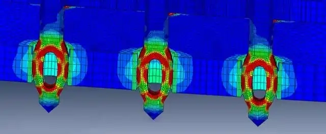
Press-fit Technology in PCBA
Press-fit technology is a solder-free connection method where a press-fit pin is inserted into a PCB’s plated-through hole. There are two main types of pins: solid pins and compliant pins, which have an elastic zone to reduce stress during insertion.
The technology ensures reliable electrical and mechanical connections by creating cold-welded interconnections between the pin and the hole, resulting in low contact resistance and long-term stability. It offers excellent mechanical strength, electrical conductivity, and automated assembly benefits, with key applications in the automotive industry.

Two Types of Press-fit Solutions
Press-fit technology has two main types: press-fit contact terminals (single pin insertion) and connector modules (mass termination). Contact terminals are usually provided in reels for flexible, manual application on PCBs. Connector modules feature custom housings with contacts and components tailored to customer needs.
Comparison: Press-fit vs Soldered Holes
With the transition to lead-free soldering, higher soldering temperatures require costly plastics like LCP, PPS, and PPA. Press-fit technology eliminates the need for soldering and expensive materials, making it a better choice for lead-free applications and automotive miniaturization.
Press-fit is ideal for large connectors and avoids issues in SMT processes, where large headers can disrupt reflow soldering. By inserting press-fit pins after soldering, you ensure reliable connections.
Advantages of Press-fit
Press-fit technology is cost-effective, swift, and reliable. It allows for pin repair and meets the IEC1709 standard, offering reliability ten times greater than soldering or IDC connections. It also prevents common soldering defects like bridges, cold solder joints, and flux residues.
Take press fit hole tolerance into consideration:
Proper dimension and tolerance control of press-fit holes ensures successful friction fits with component pins:
- Hole Diameter – Average hole size must match component pin diameter. Undersized holes prevent insertion; oversized result in loose fits.
- Hole Tolerance – ±0.05 mm tolerance typical for reliable press-fits. Tighter tolerances add cost.
- Hole Cylindricity – Hole diameter should not vary across its depth. Hourglassing or barreling will impact insertion.
- Hole Position – Hole location tolerance is guided by land pattern tolerance.
- Land Position – Lands must be aligned with their corresponding holes.
- Hole Perpendicularity – Holes must be drilled vertically to avoid skewed pins.
- Hole Axis Parallelism – All holes should be co-linear across PCB panel.
- Pin Size Tolerances – Component pin diameters have wider tolerances than PCB holes.

Benefits of Press-fit Technology
-
Fast Processing: Faster lead time compared to soldering.
-
Cost-Effective: Uses standard resins, avoiding expensive heat-stabilized materials.
-
No Thermal Treatment: Prevents heat damage to headers.
-
Flexible Design: Allows programmable pin arrays for single pin insertion.
-
Standalone Insertion: Can be applied independently.
-
Flux and Lubrication-Free: No need for flux or lubrication during assembly.
-
No Pre-Heating or Paste Printing: Eliminates solder paste printing and pre-heating.
-
Eco-Friendly: Reduces environmental impact.
-
Reliable: Avoids shading issues with large components and eliminates common soldering defects (e.g., bridges, cold solder joints, flux residues).
Recommended PCB Surface Finishes for Press Fit
Press-fit technology can be used with various surface finishes. Common choices include:
-
Chemical Gold (ENIG) or Chemical Tin
-
HAL Lead-Free
The connector manufacturer may specify the surface finish. Avoid combining gold-plated pins with chemical gold surfaces, as it increases press-in forces. Either the pin or PCB surface should be tinned to ensure smooth insertion.
Press-fit Application Scenarios
-
Stand-alone Pin Insertion: Individual pins inserted into the PCB using automated equipment, with quality control based on press-in force and depth.
-
Press-fit Pin Header: Assembly of plastic housing and pins, inserted via stitching or over-molding. The pin header can be mounted in different directions depending on assembly method.
-
Integrated Housing or Module: Components like coils, capacitors, and sensors are integrated into a single housing and mounted on the same PCB, improving assembly convenience and reliability.
-
Other Applications: Includes interconnections between two PCBs, capacitors, and IDC flat cable connectors using press-fit technology.
Press-fit Tooling
-
Single Pin Insertion Machines: Range from manual presses for small-scale production to fully automatic machines with high insertion rates and accessories for quality control.
-
Connector Seating Machines: Servo-driven all-electric presses for assembling press-fit connectors, featuring force monitoring and optional functions like Pin Presence Detection for automotive applications.
In conclusion, press fit technology has evolved and diversified in its applications and associated tooling, providing a valuable option for PCB assembly in the automotive and other industries, with clear advantages over traditional soldering methods in multiple aspects.

