Ce PCB FR4 TG170 à 6 couches est spécialement conçu pour l'industrie automobile, doté de la certification IATF16949 pour garantir une qualité et une fiabilité optimales. Sa Tg élevée (170°C) Le matériau FR4 offre une excellente stabilité thermique, essentiel pour l'électronique automobile exposée à des températures élevées dans les compartiments moteurs et dans les environnements difficiles.
Matériau FR4 TG170: La température de transition vitreuse élevée assure la stabilité dimensionnelle sous contrainte thermique, réduisant les problèmes de déformation et de performances.
1.6mm Épaisseur: Équilibre la résistance mécanique et le poids, offrant une résistance aux vibrations et aux chocs tout en favorisant l'efficacité énergétique.
1Couches de cuivre OZ: Une épaisseur de cuivre uniforme de 35 μm permet une excellente conductivité et prend en charge le routage de lignes fines (75μm ligne / espace) pour l'électronique automobile haute densité.
Finition ENIG: La finition de surface Electroless Nickel Immersion Gold empêche l'oxydation du cuivre et garantit la durabilité, joints de soudure résistants à la corrosion. Idéal pour les connecteurs automobiles nécessitant une fiabilité à long terme.
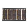
Masque de soudure noir: Améliore la visibilité des composants pendant l'assemblage, offre une résistance supérieure aux UV, et protège le PCB de l'exposition aux produits chimiques courants dans les environnements automobiles.
Prise en charge BGA: Optimisé pour les composants Ball Grid Array afin de répondre à des tolérances de soudure serrées, réduire le risque de défaillance dans les systèmes automobiles critiques pour la sécurité.
Routage précis des contours: La tolérance mécanique de ± 0,1 mm garantit un ajustement parfait aux boîtiers automobiles, avec des bords sans bavures améliorant la durabilité.
Fabrication de haute précision: Utilise l'imagerie directe au laser, perçage mécanique précis (±50μm), Cuivre autocatalytique/électrolytique, et étamage pour une définition nette des traces.
Certification IATF16949: Assure le strict respect des normes de gestion de la qualité automobile. Chaque PCB subit 100% tests électriques, Inspection des rayons X, et inspection optique automatisée pour garantir le zéro défaut.
Systèmes avancés d'aide à la conduite (ADAS): Prend en charge le routage des signaux à grande vitesse et la stabilité thermique pour les capteurs et les unités de traitement.
Systèmes d'infodivertissement: Permet des mises en page haute densité et des connexions fiables pour les processeurs et interfaces multimédias.
Modules de commande du groupe motopropulseur: Fournit une résistance aux vibrations, gestion thermique, et une capacité de courant élevée critique pour le contrôle du moteur et de la transmission.
Résumé:
Ce PCB FR4 TG170 à 6 couches offre une stabilité thermique de pointe, résistance mécanique, et performances électriques exigées par les constructeurs automobiles. Couplé à des contrôles de qualité rigoureux certifiés IATF16949, c'est un choix fiable pour ADAS, infodivertissement, et électronique du groupe motopropulseur.