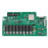
This 4-layer Tg150 PCBA is a tailored solution for power supply applications, combining advanced thermal management, high-efficiency energy conversion, and reliable performance. Engineered for industrial power supplies, server PSUs, and renewable energy inverters, the PCBA leverages a 4-layer FR4 PCB with a glass transition temperature (Tg) of 150°C to withstand moderate heat generated by power components, ensuring stable operation in environments up to 80°C. The inclusion of a customized transformer allows for precise voltage regulation and optimized power transfer, making it ideal for applications requiring high efficiency and low electromagnetic interference (EMI).
The 4-layer architecture separates power and signal domains to minimize cross-interference:
- Layer Stackup: 2 capas de señal + 2 aviones de potencia/terreno, with 1OZ copper on all layers for balanced conductivity (up to 8A per wide trace) and EMI suppression.
- Tg150 FR4 Material: Offers better thermal stability than standard FR4 (Tg130°C), reducing the risk of delamination in power-dense areas like transformer and MOSFET zones.
- Thermal Vias: Strategically placed vias under power components enhance heat dissipation, lowering hotspot temperatures by 10-15°C compared to traditional 2-layer designs.
The integrated customized transformer is designed to meet specific power requirements:
- Tailored Specs: Configurable for voltage ratios (e.g., 1:1, 2:1), power ratings (50W-500W), and frequency ranges (50kHz-1MHz) to suit applications like AC-DC adapters or DC-DC converters.
- Efficiency Optimization: Low-core-loss materials (e.g., ferrite or nanocrystalline) and precise winding techniques ensure >90% energy transfer efficiency, critical for 80 PLUS-certified power supplies.
- EMI Suppression: Shielded windings and balanced magnetic design reduce radiated emissions, helping meet EN 55032/55022 EMI standards for industrial and consumer electronics.
The PCBA undergoes a streamlined, high-precision assembly process:
- Print Paste & SPI:
- Stencil printing of lead-free solder paste (SAC305) with ±5% volume accuracy, verified by 3D solder paste inspection (SPI) to prevent bridging in fine-pitch components (e.g., 0402 passives, SOICs).
- Pick & Place & Reflujo:
- High-precision placement (±30μm) of SMT components, including power inductors, diodes, and control ICs, followed by nitrogen-assisted reflow soldering (peak 260°C) for void-free joints.
- AOI & Tht:
- Automated optical inspection (AOI) checks for misalignment or solder defects before through-hole technology (Tht) insertion of the customized transformer, connectors, and electrolytic capacitors.
- Soldadura de ondas & Soldadura con la mano:
- Lead-free wave soldering (250-260°C) ensures reliable THT joints, while manual soldering addresses delicate components or rework needs.
- Prueba funcional & QA:
- FG Test: Load testing under full/half/no load conditions verifies voltage regulation (±1%), ripple noise (<100mV), and overcurrent protection (OCP) response time (<50ms).
- X-ray Inspection: Scans transformer solder joints and hidden vias for voids (<5%) or misalignment.
- Fai & Cumplimiento: Inspección del primer artículo (Fai) includes dimensional checks and material certification (RoHS/REACH), with IPC-A-610 Class 2 compliance ensured at every stage.
- Key Checkpoints:
- SPI: Ensures solder paste volume variation <10% to prevent open circuits in power paths.
- radiografía: Verifies transformer winding integrity and BGA joint quality in control ICs.
- Thermal Cycling: -40° C a +85 ° C, 500 cycles, to simulate real-world power supply stress.
- Standards Met:
- IEC 62368 (electrical safety), EN 61000 (EMC), and UL 60950 for information technology equipment.
- Industrial Power Supplies: 24V/48V DC supplies for factory automation, with active PFC and remote monitoring via the customized transformer’s feedback loop.
- Server & Data Center PSUs: High-efficiency (≥85%) power modules supporting 1U/2U servers, featuring the transformer’s low-profile design for space-constrained enclosures.
- Renewable Energy Inverters: DC-AC inverters for solar/wind systems, with the transformer enabling galvanic isolation and MPPT (Maximum Power Point Tracking) control.
- Electrónica de consumo: Fast-charging adapters (e.g., USB PD 3.0) with compact transformers for 65W+ output in laptops and gaming devices.
- Standard Lead Time: 4-5 semanas, including PCB fabrication, component sourcing, and testing.
- Expedited Service: 2-3 weeks available for urgent projects (subject to transformer customization complexity).
- Design Support: Collaborative design services to optimize transformer specs, disposición, and thermal performance for unique power requirements.
By integrating a customized transformer with a robust 4-layer Tg150 PCBA, this solution delivers unmatched reliability and efficiency for power-critical applications. The combination of precision manufacturing, rigorous quality control, and flexible design makes it an ideal choice for engineers developing next-generation power supplies that balance performance, cumplimiento, and cost-effectiveness. Whether used in industrial machinery, data centers, or consumer devices, this PCBA ensures stable power delivery and long-term operational integrity.