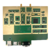
4-layer FR4 PCB is engineered for critical metro station signal monitoring controllers, where precision, durability, and electromagnetic compatibility (EMC) are essential for safe railway operations. With dimensions of 85mm×60mm and a 1.55mm thickness, the board provides a compact yet robust platform for integrating microcontrollers, communication interfaces, and signal conditioning circuitry in automated control cabinets. Constructed from FR4 material, it offers stable electrical insulation (dielectric constant εr=4.5) and mechanical strength, suitable for operation in harsh railway environments with vibration, temperature fluctuations, and electromagnetic interference.
The 0.5OZ (18μm) copper thickness on all layers balances fine-line routing density (minimum line/space: 50μm/50μm) with signal integrity, ideal for high-speed digital interfaces (e.g., CANbus, Ethernet) and low-power microcontroller circuits. The 4-layer architecture (2 signal layers + 2 ground/power planes) minimizes EMI by isolating sensitive analog signals from digital noise, critical for reliable detection of train signals, track occupancy, and safety interlocks. The Green LPI solder mask protects against moisture and contaminants, while the White silkscreen ensures clear component identification for maintenance in the field. The ENIG (Electroless Nickel Immersion Gold) surface treatment provides a corrosion-resistant, solder-friendly finish (3-5μm nickel, 0.05-0.1μm gold), ensuring long-term reliability for both surface-mount (SMT) and through-hole (DIP) components.
- EMC/EMI Mitigation:
- Ground plane stitching vias every 5mm to reduce loop inductance and suppress radiated emissions.
- Guard traces with via fences around sensitive analog inputs (e.g., track circuit receivers).
- Ferrite beads and bypass capacitors on power lines to filter switching noise.
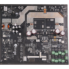
- Mixed SMT/DIP Assembly:
- SMT components (ICs, resistors, capacitors) for high-density digital circuitry.
- DIP connectors (e.g., DB9, RJ45) and relays for robust field connections and high-current switching.
- Thermal Management:
- Thermal vias under power components (e.g., regulators, drivers) to dissipate heat into ground planes.
- Copper pour areas for passive cooling, maintaining <40°C temperature rise under full load.
- High-Precision Fabrication:
- Laser direct imaging (LDI) for 50μm line/space accuracy in high-speed signal traces.
- Electroless nickel plating with ±10% thickness uniformity across all pads.
- Testing Protocols:
- 100% AOI inspection for solder mask coverage and silkscreen clarity.
- Flying probe testing for electrical continuity and isolation (≥100MΩ).
- In-circuit testing (ICT) to verify component placement and functionality.
- EMC testing per EN 50121-3-2 (railway electromagnetic compatibility standards).
- Compliance:
- UL 94V-0 flammability rating for FR4 material.
- RoHS and REACH compliant for hazardous substance restrictions.
- Track Circuit Monitoring:
Processes signals from track circuits to detect train presence and position, critical for block signaling systems.
- Level Crossing Control:
Controls safety barriers and warning signals at railway crossings, interfacing with sensors and relays.
- Train Detection Systems:
Monitors inductive loop detectors or axle counters to verify train movements and occupancy.
- Communication Interfaces:
Manages data exchange between control cabinets, central control systems, and onboard train electronics.
By integrating 4-layer EMI shielding, 0.5OZ copper precision, and ENIG durability, this PCB enables engineers to build reliable, compliant metro signal monitoring controllers. The mixed SMT/DIP assembly supports both high-density digital integration and robust field connections, while the compact form factor fits seamlessly into space-constrained control cabinets. Backed by ISO 9001:2015 certification and compliance with railway standards, this PCB ensures consistent performance in the critical safety systems that underpin modern metro operations.