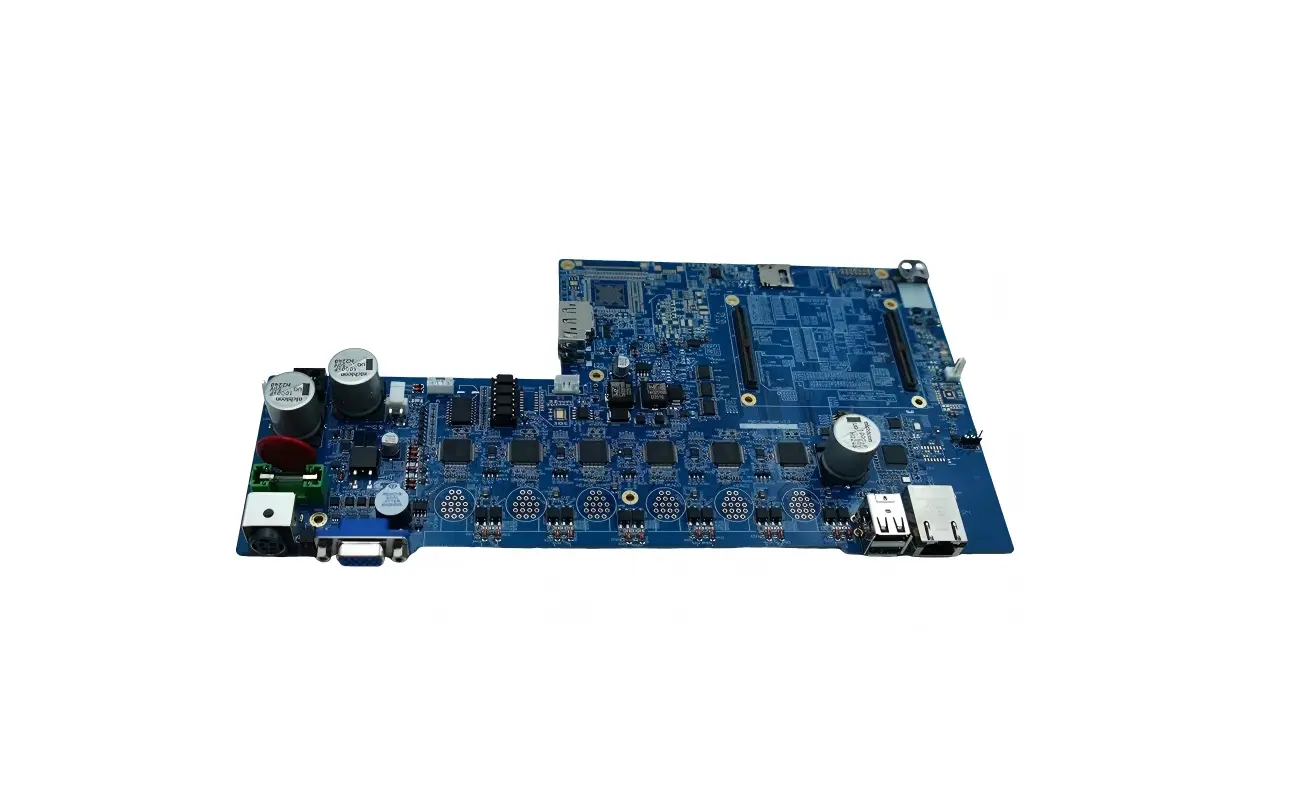
In the complex world of electronics, every printed circuit board (PCB) represents a masterpiece of precision engineering. The densely populated electronic components on it—like the “cells” of the circuit—determine device performance and stability. But these tiny parts often carry an array of cryptic markings: numbers, letters, color bands, and more. Being able to interpret these correctly and quickly can make or break a project, impact product quality, and affect manufacturing efficiency. In this article, we reveal the secrets behind resistor, capacitor, and inductor markings on PCBs, helping you confidently navigate design, debug, and production challenges.
1. Why Component Markings Are So Critical
Component markings are more than just codes—they encode the component type, key specifications (resistance, capacitance, inductance, voltage, tolerance), packaging style, and manufacturing details. Correct interpretation ensures circuit designs behave as intended, materials are purchased accurately, and assembly is efficient. Using the wrong component on a critical board can have disastrous consequences.
2. Resistors: The “Gatekeepers” of Current — Decoding Value, Tolerance & Package
Resistors are fundamental current-limiting components. Their markings vary depending on package type: through-hole (axial) versus surface-mount (SMD).
2.1 Axial Resistors: Color-Band Codes
Through-hole resistors often use color bands to indicate resistance, tolerance, and temperature coefficient. Options include 4‑band, 5‑band, and 6‑band resistors.
-
4-band resistor: First two bands are significant digits, third is multiplier, fourth is tolerance.
-
5-band resistor: First three are digits, fourth is multiplier, fifth is tolerance—used for higher precision.
-
6-band resistor: Adds a sixth band for temperature coefficient (ppm/°C), critical in precision circuits.
Example: Brown‑Black‑Red‑Gold = 10 × 100 = 1 kΩ, ±5% tolerance.
2.2 SMD Resistors: Numeric/Alphanumeric Codes
Surface-mount resistors are miniaturized and usually marked with text codes:
-
Three-digit codes: first two digits are significant, third is multiplier (power of ten). e.g. “103” = 10 × 10³ = 10 kΩ.
-
Four-digit codes: first three digits are significant, fourth is multiplier, for higher precision (e.g. “1002” = 100 × 10² = 10 kΩ).
-
R/K/M notation: ‘R’ for decimal point, ‘K’ for kilo-ohm, ‘M’ for mega-ohm. e.g. “R10” = 0.1 Ω, “4K7” = 4.7 kΩ, “2M2” = 2.2 MΩ.
-
Zero‑ohm jumper: labeled “000” or “0”—acts as a shorting link for debugging or bridging circuits.
2.3 Package Size Codes
SMD resistor sizes are indicated by codes like 0402, 0603, 0805, 1206, representing inch-based dimensions (e.g. 0603 = 0.06 in × 0.03 in). Size affects power rating and physical footprint.
3. Capacitors: The “Charge Storage” — Decoding Capacitance, Voltage & Type
Capacitors store electrical charge. Their marking conventions vary by type: ceramic, film, electrolytic, or tantalum.
3.1 Ceramic & Film Capacitors: Numeric Codes & Units
Small capacitors often use numeric codes similar to SMD resistors, but in picofarads (pF):
-
Three-digit code: first two digits significant, third is multiplier (e.g. “104” = 10 × 10⁴ pF = 0.1 µF).
-
Tolerance letters: added after code, e.g. J = ±5%, K = ±10%, M = ±20%.
-
Voltage rating: some capacitors also print values like “50V”.
3.2 Electrolytic Capacitors: Polarity, Capacity & Voltage
Used for high-capacitance filtering, electrolytic capacitors are polarized:
-
Polarity marking: through-hole types use a shorter lead (negative) and a “–”; SMD types have a color band or “+” sign on the positive side.
-
Printed values: capacity (µF) and voltage (V), e.g. “220 µF 16V”.
3.3 Tantalum Capacitors: Color Bands & Alphanumeric Codes
Tantalum capacitors offer high capacity in small size:
-
Color stripe: indicates the positive lead.
-
Code marking: combinations like “106K 25V”, where letters represent capacitance tolerance, numbers represent capacitance/voltage.
3.4 Package Size Codes
Similar to resistors, SMD capacitors use size codes such as 0402, 0603, 0805, which impact performance and layout.
4. Inductors: The “Magnetic Field Controllers” — Reading Inductance & Current Ratings
Inductors store energy magnetically. Their markings are simpler but must be distinguished from resistors.
4.1 Color‑band Inductors
Some through-hole inductors use color bands similar to resistors. Distinguish them by shape, size, and placement.
4.2 SMD Inductors: Numeric Codes or Dots
Surface-mount inductors may have:
-
Numeric codes: similar to capacitors/resistors but in nH or µH (e.g. “R47” = 0.47 µH, “100” = 10 µH).
-
Color dots: small colored markings to indicate inductance.
4.3 Power Inductors: Direct Markings
Larger power inductors often have markings like “4.7 µH 3A” to show inductance and current rating clearly.
5. Other Common Component Markings
PCBs also include components beyond resistors, capacitors, and inductors:
-
Diodes: marked by part number (e.g. 1N4007) plus polarity stripe. LEDs have long lead = positive, short lead = negative, or a flat edge on the negative side.
-
Transistors: labeled with codes like S8050 or 2N3904; tiny packages might use just 2–3 characters—refer to datasheets to map pins (B, C, E).
-
Integrated Circuits (ICs): print manufacturer logo, part number, batch codes, plus a “pin 1” indicator (dot, notch, or chamfer).
6. Risks of Misreading & Fully Hong’s Solution
Misreading component markings can have severe consequences:
-
Circuit failure: incorrect component value stops functionality.
-
Performance dropout: issues like noise, power inefficiency, or signal distortion.
-
Reliability risk: mismatched specs can lead to early failure.
-
Safety hazards: wrong components in power circuits may cause overheating or fire.
-
Increased costs: misloaded boards result in rework and delayed delivery.
Fully Hong, a leader in PCB and PCBA services, understands the critical importance of accurate component identification. We ensure precision at every stage:
-
✅ DFM/DCR validation: engineers review component compatibility and manufacturability during design to prevent early errors.
-
✅ Strict sourcing: components sourced from OEMs or authorized distributors are verified by visual inspection, dimensional checks, electrical testing, and even X‑ray for traceability.
-
✅ Advanced automated assembly: SMT production lines with high‑precision placement and AOI inspection catch misplacement, polarity errors, and missing parts.
-
✅ Comprehensive quality controls: AOI, X‑ray, ICT (in‑circuit test), and FCT (functional test) ensure each PCBA meets spec.
-
✅ One-stop service: from PCB design to component procurement, assembly, testing, and final integration—Fully Hong streamlines your process with expert support.
Choose Fully Hong for precision, efficiency, and reliability. We don’t just deliver high-quality circuit boards and assemblies—we provide end-to-end technical support and stringent quality assurance. Whether you need multi-layer PCBs or high-precision PCBA assembly, we tailor solutions to meet the highest industry standards.
📢 Act now—accelerate your electronics projects!
For component label inquiries or to find a trusted PCB/PCBA partner, connect with Fully Hong. Click below for a customized solution or consult with our experts. Let us help you turn innovation into high-performing electronics!


Leave a reply