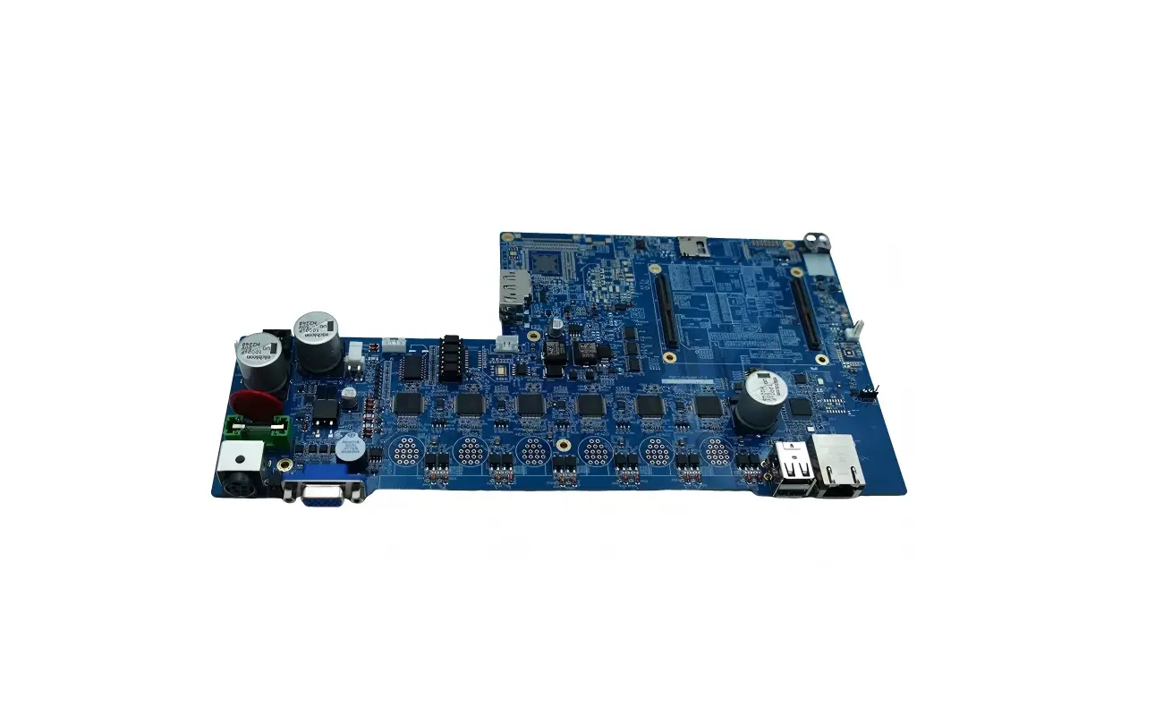
Im Bereich der Präzisionselektronikfertigung, der Platine (Gedruckte Leiterplatte) ist der Grundstein aller Hardware. Jedoch, Selbst die erfahrensten Ingenieure können aufgrund eines scheinbar unbedeutenden Details vor Herausforderungen stehen – der korrekten Identifizierung und Installation polarisierter Komponenten. Eine verpolte Diode oder ein falsch herum eingebauter Elektrolytkondensator können alles Mögliche verursachen, von Störungen im Schaltkreis bis hin zu Kurzschlüssen, Rauch, oder sogar Explosionen, Dies führte zu erheblichen wirtschaftlichen Verlusten und Projektverzögerungen.
1. Die Identifizierung der Polarität ist entscheidend! Die hohen Kosten einer falschen Installation verstehen
Stellen Sie sich das vor: Sie haben viel Zeit investiert, Geld, und Aufwand, ein innovatives Produkt zu entwickeln, nur um während der PCBA mit Chargenfehlern oder Rückrufen konfrontiert zu werden (Leiterplattenbaugruppe) aufgrund eines einfachen Polaritätsfehlers in einer Komponente. Dies ist nicht nur ein finanzieller Verlust, sondern auch ein schwerer Schlag für den Ruf der Marke. Wie der Name schon sagt, Polarisierte Komponenten haben eine interne Struktur, die die richtige Richtung des Stromflusses oder der Spannungsanlegung vorgibt. Einmal umgekehrt angeschlossen:
-
Diode vertauscht: Eine normale Diode blockiert den Strom und leitet nicht; Eine Zenerdiode kann beschädigt werden.
-
Elektrolytkondensator verpolt: Bestenfalls, Leckage und verminderte Leistung; schlimmstenfalls, Überhitzung, Schwellung, oder Explosion, Dies stellt eine Gefahr für Bediener und in der Nähe befindliche Komponenten dar.
-
Integrierter Schaltkreis (IC) umgedreht: Bestenfalls, es wird nicht funktionieren; schlimmstenfalls, dauerhafte Schäden am Chip selbst oder anderen angeschlossenen Präzisionskomponenten verursachen.
Diese Risiken machen die Polaritätserkennung zur unzerstörbaren „Lebensader“ im Leiterplattenbestückungsprozess. Das korrekte Erkennen von Markierungen gewährleistet einen reibungslosen Projektablauf, zuverlässige Produktleistung, und Benutzersicherheit.

2. Eingehende Analyse gängiger Markierungen polarisierter Komponenten
1. Dioden
Eine Diode ist ein Halbleiterbauelement, das Strom nur in eine Richtung leitet und über zwei Anschlüsse verfügt: Anode (A) und Kathode (K). Strom fließt nur von der Anode zur Kathode.
Oberflächenmontierte Diode (SMD-Diode):
-
Farbband-/Ringmarkierung: Dies ist die gebräuchlichste Markierungsmethode. Typischerweise, Auf dem Diodenkörper befindet sich ein weißer oder schwarzer Ring, der das Kathodenende anzeigt. Das gegenüberliegende Ende ist die Anode.
-
Symbolmarkierung: Auf der Oberfläche einiger SMD-Dioden ist das Symbol der Diodenschaltung aufgedruckt (ein Dreieck mit einer vertikalen Linie). Die Linie gibt die Kathodenrichtung an.
-
Paketkerbe: Bei einigen Sonderverpackungen kann die Kathode durch eine Kerbe oder einen Punkt gekennzeichnet sein.
Durchgangsdiode:
-
Farbbandmarkierung: Ähnlich wie SMD-Dioden, Durchsteckdioden haben normalerweise einen zylindrischen Körper mit einem Farbband oder Silberring, der die Kathode markiert.

- Leitungslänge: Für bestimmte LEDs (Leuchtdioden), wenn neu, die längere Leitung ist die Anode, und die kürzere Leitung ist die Kathode. Jedoch, Beachten Sie, dass nach dem Trimmen der Leitungen oder mehrfacher Verwendung, Diese Methode ist möglicherweise nicht mehr zuverlässig.

Lange und kurze Diodenstifte
-
Abgeschrägte/flache Kante: Einige LED-Pakete haben seitlich eine flache oder abgeschrägte Kante, was normalerweise dem Kathodenanschluss entspricht.

Die flache Form der Diode stellt den Minuspol dar
-
Interne Struktur: Für transparent vergossene LEDs, Im Inneren befinden sich eine große „fahnenförmige“ Struktur und eine kleinere „pfostenförmige“ Struktur. Die größere ist die Kathode (Negativ), und die kleinere ist die Anode (positiv).
2. Elektrolytkondensatoren
Elektrolytkondensatoren, aufgrund ihrer relativ großen Kapazität und Größe, spielen eine wichtige Rolle in Kreisläufen wie der Energiespeicherung und -filterung. Es handelt sich um typische polarisierte Bauteile und dürfen niemals vertauscht angeschlossen werden.
Zylindrische Durchsteck-Elektrolytkondensatoren:
-
Negativer Markierungsstreifen: Die negative Seite des Kondensators hat normalerweise einen dunklen Streifen (wie Schwarz oder Grau) mit einem „−“-Zeichen oder Pfeil gekennzeichnet. Die diesem Streifen entsprechende Leitung ist der Minuspol.

-
Leitungslänge: In brandneuen Elektrolytkondensatoren, die längere Leitung ist der Pluspol, und die kürzere Leitung ist der Minuspol. Dies steht im Widerspruch zur LED-Konvention und erfordert besondere Aufmerksamkeit. Ähnlich, nach dem Trimmen der Leitungen, Diese Methode wird unzuverlässig.
Oberflächenmontierte Elektrolytkondensatoren (SMD-Elektrolytkondensatoren) / Tantal -Kondensatoren:

-
„+“-Zeichen oder Farbband: Oberflächenmontierte Elektrolytkondensatoren und Tantalkondensatoren haben normalerweise eine „+“-Zeichen oder ein breites Farbband auf den Körper gedruckt. Die Seite, die dieser Markierung entspricht, ist der Pluspol. Im Gegensatz zu Durchgangskondensatoren, bei denen der Streifen den Minuspol anzeigt, Diese Markierung kennzeichnet den Pluspol. Eine sorgfältige Unterscheidung ist unerlässlich.
Paketfase: Einige Tantalkondensatoren verwenden möglicherweise auch eine abgeschrägte oder abgeschrägte Kante, um den Pluspol anzuzeigen.

3. Integrierte Schaltungen (ICs)
Obwohl ein IC im Wesentlichen ein Chip ist, Die richtige Ausrichtung auf der Leiterplatte ist entscheidend, da die Pinbelegung festgelegt ist. Falsches Einsetzen kann zu Fehlfunktionen oder sogar Schäden führen.
Stift 1 Identifikation: Fast alle ICs geben ihren ersten Pin an (Stift 1) durch besondere Markierungen. Einmal Pin 1 befindet, Die anderen Stifte sind normalerweise im Gegenuhrzeigersinn zu erkennen. Gemeinsamer Pin 1 Markierungen enthalten:
-
Punkt: Ein kleiner versenkter oder aufgedruckter Punkt in der Nähe von Pin 1 auf der Chipoberfläche.

-
Kerbe/Nut: Eine Seite des Chips hat eine U-förmige oder V-förmige Kerbe, und das Ende, an dem sich die Kerbe befindet, entspricht normalerweise Pin 1.

- Abgeschrägte/abgeschrägte Ecke: Für einige quadratische Pakete, Eine Ecke ist abgeschrägt oder abgeschrägt, und diese Ecke zeigt die Richtung von Pin an 1.

- Pin-Siebdruckmarkierung: Auf der PCB-Siebdruckschicht, Normalerweise gibt es einen rechteckigen Umriss, der der Form des IC-Gehäuses entspricht. Der Standort von Pin 1 ist mit einem Punkt gekennzeichnet, Dreieck, oder fette Linie, entsprechend der Markierung auf dem IC selbst.

4. Andere gängige polarisierte Komponenten
Leuchtdiode (LED): Abgesehen von der oben erwähnten Leitungslänge und flachen Kante, Einige LEDs haben eine kleine Fase oder Kerbe am unteren Rand des Gehäuses, was normalerweise der Kathode entspricht.

-
Induktoren: Obwohl die meisten Induktoren nicht polarisiert sind, Einige gekoppelte Induktivitäten oder Transformatoren weisen möglicherweise „Punkt“-Markierungen auf, die auf die „gleichnamigen Anschlüsse“ der Primär- und Sekundärwicklung hinweisen. Dies ist entscheidend für die Leistung von Hochfrequenz- oder Schaltnetzteilschaltungen.

- Anschlüsse: Viele Anschlüsse (insbesondere mehrpolige Steckverbinder) verfügen über Kodierungsdesigns, um falsches Stecken zu verhindern, aber es ist immer noch notwendig, Pfeile zu verwenden, Dreiecke, oder Pin 1 Siebdruckmarkierungen auf dem Steckerkörper sorgen für die korrekte Einsteckausrichtung.

-
Batterien/Batteriehalter: Die Batterien selbst sind mit deutlichen Markierungen „+“ und „–“ versehen, und die Batteriehalter verfügen in der Regel auch über entsprechende Siebdruckmarkierungen.

3. Wie [Voll Hong] Stellt sicher, dass bei Ihren PCBA-Projekten keine Polaritätsfehler auftreten
Bei [Voll Hong], Wir wissen, dass die richtige Polarität der Komponenten für die Produktqualität von entscheidender Bedeutung ist. Als führender Komplettanbieter vom PCB-Design bis zur PCBA-Montage, Wir verwenden mehrere Prüfungen, um sicherzustellen, dass es keine Polaritätsfehler gibt:
-
Gründliche DFM-Überprüfung: Unsere Ingenieure prüfen Ihre Entwürfe sorgfältig, um die Markierungen und Symbole aller polarisierten Komponenten zu überprüfen, Mögliche Polaritätsprobleme frühzeitig erkennen.
-
Erweiterte automatisierte Montage & Inspektion: Einsatz erstklassiger SMT-Linien und AOI-Systeme, Wir platzieren Komponenten genau und prüfen sie auf Polaritätsfehler, Fehlplazierungen, oder fehlende Teile.
-
Manuelle Qualitätsprüfungen: Um sicherzustellen, dass kritische Komponenten einer zusätzlichen manuellen Prüfung unterzogen werden 100% Genauigkeit. Unsere ISO 9001 Das Qualitätssystem garantiert eine strenge Prozesskontrolle.
-
Zuverlässige Lieferkette: Um Klarheit zu gewährleisten, beziehen wir ausschließlich von zertifizierten Lieferanten, Korrekte Polaritätsmarkierungen an den Bauteilen.
4. Warum wählen [Voll Hong]?
Vom Design bis zur Produktion, [Voll Hong] liefert:
-
Kompletter One-Stop-Service: Design, Herstellung, Beschaffung, Montage, und Tests – alles optimiert, um Ihre Markteinführungszeit zu verkürzen.
-
Hohe Präzision & Zuverlässigkeit: Modernste Ausrüstung und strenge Kontrollen eliminieren Polarität und andere Mängel.
-
Schnell, Maßgeschneiderter Support: Wir bieten maßgeschneiderte Lösungen für jede Projektgröße und reagieren schnell.
-
Kosteneffizienz: Durch vertikale Integration und effizientes Beschaffungsmanagement bleiben die Kosten wettbewerbsfähig, ohne dass die Qualität darunter leidet.
Beseitigen Sie Polaritätsfehler und stellen Sie den Erfolg Ihres Produkts sicher! Kontakt [Voll Hong] für maßgeschneiderte PCB- und PCBA-Lösungen – schnelle Prototypen oder Großserienfertigung, Wir liefern Qualität und Schnelligkeit, um Ihnen zu helfen, den Markt zu erobern.
Fordern Sie noch heute ein kostenloses Angebot an oder laden Sie unser Whitepaper herunter!


Hinterlasse eine Antwort