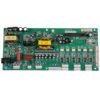
BMS board revolutionizes drone charging station management by integrating precise power control, multi-protocol communication, and intelligent battery management, ideal for commercial drone fleets, logistics hubs, and autonomous aerial systems. The core design emphasizes eight 3A constant voltage constant current outputs, each optimized for parallel charging of drone batteries while maintaining charge consistency and efficiency. The constant voltage (CV)/constant current (CC) charging control automatically switches between charging phases: CC mode for rapid charging at 3A until the battery approaches full capacity, then CV mode to maintain voltage stability and prevent overcharging—critical for extending lithium battery lifespan in high-turnover drone operations.
- Multi-Protocol Communication:
- RS485: Enables long-range (up to 1.2km) communication for central monitoring of multiple charging stations.
- Serial port (UART): Supports direct connection to drone docking systems for real-time charge status updates.
- USB interface: Allows local configuration via PC software, the firmware updates, and data logging.
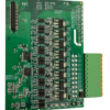
- 8-Channel 3A Power Output:
- Independent PWM control for each channel, achieving ±1% current/voltage accuracy.
- Support for 12-24V input voltage, compatible with common drone battery chemistries (LiPo, Li-ion).
- Comprehensive Power Management:
- Overcurrent protection: Instantaneous shutdown at >3.3A per channel to prevent short circuits.
- Overvoltage/undervoltage protection: Monitors each battery voltage, disconnecting when outside safe range (e.g., <2.5V or >4.35V for LiPo).
- Thermal management: Built-in NTC thermistors detect overheating (≥75°C), reducing output current to prevent thermal runaway.
- Voltage Monitoring & Balance Management:
- 16-bit ADC for real-time voltage sampling (resolution: 1mV) across all channels.
- Active cell balancing (100mA per cell) to equalize battery packs, minimizing capacity degradation over cycles.
- Rugged Hardware:
- 4-layer FR4 PCB with 1.6mm thickness and 2OZ copper for low impedance and heat dissipation.
- Metal heat sink on power MOSFETs to maintain <40°C temperature rise under full load.
- EMI/EMC Compliance:
- Meets FCC Part 15 Class B for electromagnetic emissions, suitable for indoor drone hubs.
- Transient protection (TVS diodes) on all communication ports to withstand electrostatic discharge (ESD).
- Reliability Features:
- Redundant power input (DC 12-24V + optional UPS backup) for uninterrupted charging.
- Battery-backed real-time clock (RTC) to log charging events during power outages.
- API & Protocol Support:
- Modbus RTU over RS485 for integration with SCADA systems.
- Custom JSON API over USB for drone fleet management software (e.g., scheduling charging cycles, prioritizing high-priority drones).
- Monitoring Dashboard:
- Web-based interface displays real-time charge status, historical data, and alarm notifications (e.g., failed charging channel, unbalanced battery).
- Logistics & Delivery Drones:
Manages charging for fleets in distribution centers, ensuring quick turnaround for package delivery.
- Agricultural Drones:
Enables 24/7 charging for crop monitoring drones in remote farms, with SMS alerts for maintenance needs.
- Security & Surveillance Drones:
Maintains ready-to-fly batteries for drones patrolling industrial sites or urban areas.
- Emergency Response Drones:
Prioritizes charging for medical supply or search-and-rescue drones, with priority charging queues.
By integrating 8-channel CC/CV charging, multi-interface communication, and robust protection features, this BMS board ensures efficient, safe drone battery management in high-demand environments. Its combination of precision power control, real-time monitoring, and industrial reliability makes it a strategic choice for drone operators seeking to optimize fleet uptime and battery lifespan. Backed by a 2-year warranty and 24/7 technical support, the board simplifies integration into existing charging station infrastructure while enabling future upgrades for evolving drone technologies.

")